
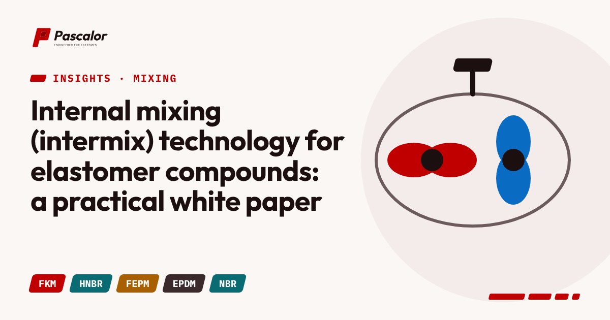
Almost every compound that ends up as a seal, hose, belt or tyre passed through an internal mixer first. The machine, often called a Banbury after its inventor's company or an "intermix" after the intermeshing-rotor design, is a closed chamber with two counter-rotating rotors, a loading chute, a ram that presses the batch down, cooled walls and a drop door. Its job is simple to state: turn separate ingredients into one uniform compound without damaging the polymer or starting the cure.
What mixing must achieve
- Incorporation: wetting the filler with polymer.
- Dispersion: breaking filler agglomerates into small aggregates.
- Distribution: spreading everything evenly through the batch.
- Plasticisation: reducing viscosity so the compound can be processed.
- Protection: keeping temperature below the point where curatives react or the polymer degrades.
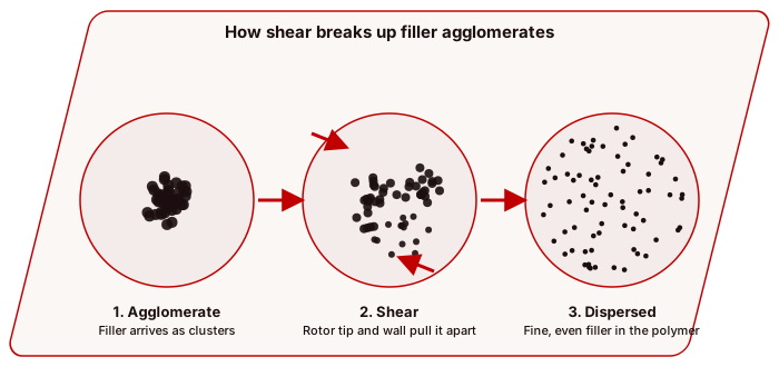 Figure. Filler clusters are pulled apart where the rotor tip passes close to the chamber wall.
The machine and its variables
| Variable | Effect | Typical trade-off |
|---|---|---|
| Rotor type | shear intensity and distributive mixing | tangential rotors are flexible, intermeshing rotors give tighter temperature control and faster mixing |
| Rotor speed | shear rate and energy input | high speed shortens time but raises temperature |
| Fill factor | how much of the free chamber volume the batch occupies | too low, the ram loses effect. Too high, the batch cannot circulate |
| Ram pressure | contact of the batch with the rotors | higher pressure speeds mixing and raises temperature |
| Chamber and rotor temperature | starting temperature, heat removal | cold walls help control, but very cold rubber is hard to bite |
| Mixing sequence | what meets what, and when | decides dispersion, scorch safety and oil take-up |
| Dump condition | temperature, power or time that ends the stage | decides batch-to-batch consistency |
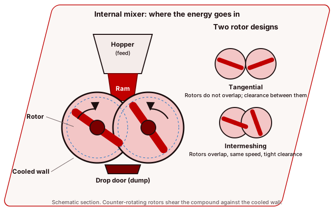 Figure. Section through an internal mixer, with the two common rotor designs.
Rotor design
Tangential rotors run side by side with a clearance, and can be run at even speed or at friction ratio. They are versatile for masterbatches, remills and finals. Intermeshing rotors overlap and must run at even speed. They use a smaller fill, give better dispersion in many compounds and extract heat well through the rotors, so they hold temperature down, which helps heat-sensitive recipes.
Fill factor and ram
A common range is roughly 65 to 80 % of chamber volume for tangential machines and a bit lower for intermeshing ones, but the right number depends on the compound. Stiff, high-viscosity compounds like HNBR and FKM often run at a lower fill factor. Ram pressure should keep the ram seated against the batch. A ram that floats means too little material or too much air.
Temperature control
Heat comes from friction and shear in the compound. It is removed by the cooling water in the walls, rotors and door. The compound temperature, not the water temperature, is what the polymer and the curatives feel. Many mixing specifications therefore end the stage on dump temperature or on a combination of energy and temperature, not on time alone.
Building a mixing cycle
A cycle is a recipe for the machine. A typical multi-stage cycle looks like this.
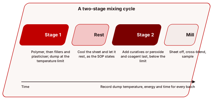 Figure. A two-stage cycle: stage 1, rest, stage 2, mill.
- Stage 1, masterbatch: polymer first, soften, then fillers and oils in two or three additions, sweep, dump at a high enough temperature to disperse filler, below the point of polymer damage.
- Cooling and resting: sheet off on a mill or extruder, cool and rest. Resting allows filler-polymer interaction and lets viscosity settle.
- Optional remill: a second pass without curatives to improve dispersion or reduce viscosity.
- Final or productive stage: add curatives (and, for sensitive systems, add them on a mill or in a cool mixer), at a low dump temperature.
- Sheeting and cooling: quick cooling prevents scorch in the stack. Label with batch number, time and temperature.
Mixing methods
- Conventional (right-side-up): polymer first, then fillers and oil.
- Upside-down: fillers first, polymer on top. Gives fast incorporation of high loadings, with care about dust and temperature.
- Y-mixing and slush mixing: two premixes combined, or oil and filler premixed.
See the separate article on mixing sequences.
Mixing different polymer families
| Compound family | Main mixing concern |
|---|---|
| FKM | stiff, sticky, scorch-sensitive if curatives are present, corrosive by-products if overheated, cool dump |
| HNBR | very high viscosity, peroxide scorch, dispersion of filler and coagent |
| FEPM | peroxide scorch, stiff gum at low temperature |
| EPDM | high oil and filler loadings, fill factor and sequence for oil take-up |
| NBR | bound filler and plasticiser, scorch with sulfur systems |
| Silicone (VMQ) | usually mixed on mills or kneaders, not in the usual high-shear internal mixer, dispersion of silica and structure control |
Measuring whether it worked
The batch is only good if the tests say so: Mooney viscosity, rheometer curve (ML, MH, ts2, t90), density and, for dispersion, a visual or image-based rating of filler dispersion. Keep control charts for each. Drift in ML or ts2 is the first warning that raw materials, rotor wear or process settings changed.
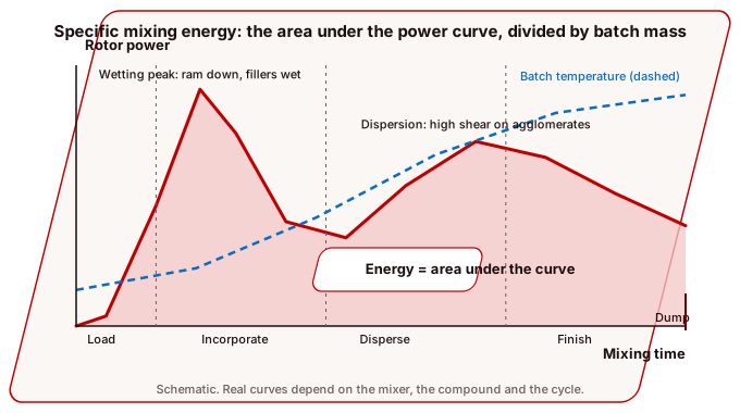 Figure. Mixing power and specific energy. The area under the power curve, divided by the batch mass, is the specific energy put in.
What this means for HPHT and HPLT compounds
Extreme-duty compounds amplify mixing errors. Poor dispersion in an HPHT seal shows up as low tear strength and poor decompression resistance. Too much shear heat in an HPLT compound that relies on a plasticiser can drive some of the plasticiser out. A written mixing procedure, controlled raw-material lots and recorded batch parameters are the foundation of repeatable extreme-performance rubber.
Sources and further reading
- Ciullo and Hewitt, The Rubber Formulary (1999), the processing overview on mixing, masterbatching, remilling and finish mixing.
- IIT Kharagpur Rubber Technology Centre lecture material on rubber compounding and rheology.
- Alpha Technologies, public technical article on factors that affect an internal mixer batch (rotor type, speed, ram pressure, fill factor, sequence).
- 3M Dyneon, public fluoroelastomer datasheet mixing notes (order of addition, bands on the mill, dry ingredients blended before addition).