
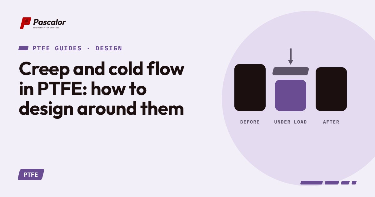
Creep is slow deformation under constant stress. Cold flow is the same effect seen at room temperature. In PTFE it is large, and it grows with load, temperature and time.
Where it shows up
- Gaskets. Bolt load relaxes and the joint leaks after thermal cycles.
- Valve seats. The seat flows into the flow path or away from the ball.
- Seals. A tight groove that squeezes PTFE slowly loses contact force.
- Back-up rings. Under pressure the ring can extrude into the clearance.
- Threaded plastics. Torque falls as the thread flows.
Ways to reduce it
- Fill it. Glass, carbon fibre, bronze or modified PTFE grades cut creep by a large factor.
- Use modified PTFE. The comonomer gives a denser structure.
- Reduce stress. Use a wider sealing area and lower unit pressure.
- Confine the PTFE. A closed groove with controlled volume stops flow. Leave room for thermal expansion.
- Add a spring or elastomer energiser. The spring supplies the load, the PTFE supplies the sealing face.
- Re-torque after the first thermal cycle, using a plan agreed with the supplier.
- Use live-loaded fasteners (spring washers) in gasketed joints.
Reading creep data
Datasheets give deformation under load (for example ASTM D621: percent deformation after 24 hours at 7 MPa). Compare grades at the same stress and temperature. Remember that deformation at room temperature can double by 100 degrees C.
Thermal cycles
A part that creeps while hot shrinks away when cold, because it does not recover its old volume. Joints that seal at start-up can leak after the first cooling. This is one reason PTFE joints are re-tightened or designed with energisers.
Design checks
- What is the steady stress at temperature?
- Does the part have a closed or open groove?
- What happens after a hot-cold cycle?
- Is the time to failure measured in hours, months or years?
If any answer is unclear, build a short pilot including thermal cycling.
About this article. It is original writing prepared from public sources, standards and general industry practice. It is not a copy of any book or standard and it is not engineering advice. Confirm values against the current edition of the standard and test in your own application. Only analyse material you own or are entitled to analyse.