
Sliding PTFE parts fail by heat and wear. Two quantities describe the duty: contact pressure P and sliding velocity V.
The PV product
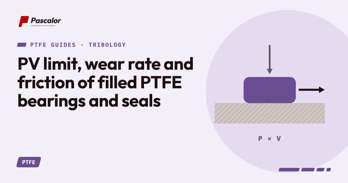
PV is the contact pressure multiplied by sliding speed. It is proportional to the frictional heat generated per unit area, so it is the first screening number for any dry-sliding bearing or rotary seal.
Typical orders of magnitude (indicative only, at room temperature, hard smooth counterface; always confirm with supplier data):
| Material | Approximate PV limit |
|---|---|
| Virgin PTFE | about 0.04 MPa m/s |
| Glass-filled PTFE | about 0.3 to 0.5 MPa m/s |
| Carbon-graphite filled PTFE | about 0.4 to 0.7 MPa m/s |
| Bronze-filled PTFE | up to about 0.6 to 1 MPa m/s |
Limits fall as temperature rises, because the material softens and heat is harder to remove. They also have separate limits for pressure alone (creep) and for velocity alone (heat).
Wear rate
A working model is: wear depth = k x P x V x time, where k is a specific wear rate. Unfilled PTFE has k of the order 10-13 to 10-12 m3/Nm (high). Good filled grades sit near 10-16 to 10-15 m3/Nm, up to a thousand times lower. Use it for ranking, not for exact life prediction. Real wear depends on counterface, film formation, temperature and lubrication.
Friction
PTFE friction falls as pressure increases, from around 0.1 at very low load toward 0.04 at high load. Static friction is similar to or slightly above dynamic, which is why PTFE is relatively free of stick-slip. Fillers raise friction somewhat. Graphite and MoS2 keep it low.
The transfer film
Sliding PTFE deposits a thin film on the counterface. Wear then occurs mostly between PTFE and PTFE, not metal. A smooth, hard counterface lets this film form and stay. A rough one (above about Ra 0.4 micrometres) shreds the film. A mirror finish below Ra 0.1 can prevent adhesion of the film and also raise wear.
Designing for heat
- Keep PV well below the limit at the real temperature.
- Provide a metal path for heat to escape. Thin PTFE liners on metal backing run cooler than solid bushings.
- For rotary shafts, check surface speed at the seal diameter, not rpm.
- Vent trapped gas so the contact does not insulate itself.
Practical limits
Dry running of simple lip seals is limited to low surface speed. Spring-energised seals with a suitable filled jacket can run much faster, and some designs run lubricated by the fluid.