


- Document
- PP-TB-001
- Version
- 0.1
- Date
- 2026-10-23
- Type
- Technical briefing
1. Purpose and status of this document
This briefing explains rapid gas decompression (RGD) testing for buyers, engineers and seal makers who need to read or order RGD test reports. It is a technical explainer built from public sources and standards that we name in section 10. It is not a test report, a certificate or a copy of any standard. It contains no test results for any Pascalor compound. Where sources disagree, we show the disagreement and do not choose a winner. Before any value in this document is used in a specification or a claim, it must be checked against the current edition of the relevant standard.
2. Summary
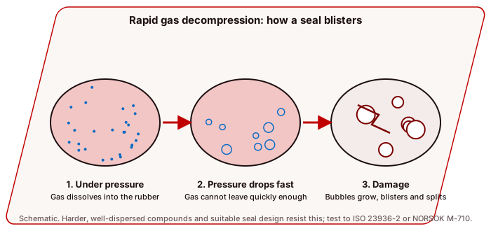
- RGD damage occurs when gas dissolved in a seal under high pressure cannot leave quickly enough as the pressure falls. It forms bubbles, then cracks and blisters, inside the rubber.
- The industry reference is the RGD test in NORSOK M-710 and in ISO 23936-2 (Annex B). Operators sometimes use other, harsher conditions. Public sources disagree on some parameters, so section 4 shows them side by side.
- Seals, usually O-rings, are soaked in a high-pressure gas mixture at temperature, decompressed repeatedly, cut open, and examined under magnification. Damage is rated from 0 to 5, and the worst rating for the material is reported.
- A rating belongs to one compound, one seal size and one set of test conditions.
- Any claim needs the standard, edition, conditions, seal size, rating, laboratory and report number.
3. The mechanism in brief
Gas dissolves into rubber in proportion to the pressure applied. Carbon dioxide is far more soluble than methane in most elastomers. When pressure falls, gas inside the seal must diffuse out through the surface. If the pressure falls faster than the gas can leave, the dissolved gas separates inside the rubber as bubbles. Bubbles that grow and link become cracks, and cracks near the surface become blisters. Large cracks cut across the cross-section.
The main factors are gas composition, pressure, temperature, decompression rate, seal cross-section, and the compound itself: modulus, tear strength, filler and cure system. Thicker sections hold gas longer, so they suffer more damage under the same decompression.
4. Test routes as summarised in public sources
Public sources describe RGD tests differently. The table below is a map of what is commonly cited. It is not a substitute for the standard. Parameters differ between sources, and the sources do not always say which edition of NORSOK M-710 they describe. Cells that read "not stated" mean the source we read does not give the value.
| Parameter | A: James Walker (NORSOK M-710 Annex B, Rev 3, and ISO 23936-2) | B: CDI Energy Products (ISO 23936-2 Annex B) | C: ETS note, NORSOK column | C: ETS note, ISO 23936-2 column | C: ETS note, "Total" column | D: Trelleborg (NORSOK M-710) |
|---|---|---|---|---|---|---|
| Gas mixture | CH4 90% / CO2 10% | CH4 90 mol% / CO2 10 mol% | CO2:CH4 10:90 and 3:97 | Written as "10:90 CO2:N2" in the source; the other sources give CH4 | 20:80 | 3% CO2, 10% CO2 or 100% CO2, balance CH4 |
| Temperature | 100 °C | 100 °C | 100, 150 or 200 °C | 100 °C | 75 °C | 100, 150 or 200 °C |
| Pressure | 150 bar | 15 MPa (150 bar) | 150, 200 or 300 bar | 150 bar | 190 bar | 15, 20 or 30 MPa |
| Exposure | Not stated | 8 decompression cycles over 7 days | 72 h | 68 h | 48 h | At least 72 h |
| Decompression rate | 20 to 40 bar/min; the source says 20 is the official figure | Not stated | 20 to 40 bar/min | 20 bar/min | "90 sec max (126.6)" | 2 to 4 MPa/min (20 to 40 bar/min) |
| Cycles | 8, with 1 h dwell between cycles | 8 | 10 | 8 | 5 | 10 |
| Seal | 5.33 mm cross-section O-ring | AS568-325 | 2-325 | 2-312 to 2-329 | Size not stated | Not stated |
| Compression | Not stated | Not stated | 20% | 15% | 5 to 15% | Not stated |
| Volume fill | Not stated | Not stated | 80 to 85% | 85% | 70% | Not stated |
| Samples | 3 tested together | Not stated | Not stated | Not stated | Not stated | Not stated |
Source A adds two operator routes. The "Total" route (GS EP PVV 154/156) uses 80/20 methane/CO2, 190 bar, 75 °C, about 127 bar/min, with a 5.33 mm or 6.99 mm cross-section. Shell MESC 85/301 uses 150 bar, 150 °C and 40 bar/min, which that source says makes a pass extremely difficult. Source A also notes that larger O-rings need more cuts (four cuts for a BS-312 ring, eight for a BS-329), and that more cuts make a high rating harder to achieve.
What the table shows, and what it does not
- Sources C and D describe the same broader set of conditions for NORSOK M-710: three temperatures, three pressures, at least 72 h and ten cycles. Sources A and B tie the narrower set (100 °C, 150 bar, 8 cycles) to NORSOK M-710 Edition 3 and to ISO 23936-2 Annex B. Source A states that the two standards are identical in this respect.
- None of the sources says which edition the broader set belongs to. An older edition is a plausible explanation, but we have not confirmed it. Do not assume either way.
- Source C notes that the gas for NORSOK is ambiguous in its own table, which lists both 10:90 and 3:97.
- Source D says pressure is held for 23 to 24 hours per cycle, which does not obviously fit a 72 h total with ten cycles. We have kept the statement as written and flagged it for checking.
How to use this table. Treat it as a list of questions to ask. When a supplier says "NORSOK RGD tested", ask which edition, which gas, which temperature and pressure, which decompression rate and which O-ring size.
Standards and operator documents named by the sources
- NORSOK M-710 (qualification of non-metallic sealing materials and manufacturers).
- ISO 23936-2, Annex B (normative RGD procedure) and Annex F (informative note on RGD). The table of contents is public; the clause text is not.
- Operator documents named by Source A: Total GS EP PVV 154/156, and Shell MESC 85/301.
5. Rating the damage
After the test, each O-ring is cut into radial sections and examined at a magnification of at least ten times. Each section receives a rating from 0 to 5. The scale below follows Source A and should be checked against the standard. Source B does not reproduce the scale; it shows only the resulting four-digit codes.
| Rating | Description in Source A | Result |
|---|---|---|
| 0 | No internal cracks, holes or blisters of any size | Pass |
| 1 | Fewer than four internal cracks, each shorter than half the cross-section, with total crack length below the cross-section | Pass |
| 2 | Fewer than six internal cracks, each shorter than half the cross-section, with total crack length below 2.5 times the cross-section | Pass |
| 3 | Fewer than nine internal cracks, with at most two between half and 80% of the cross-section | Pass |
| 4 | More than eight internal cracks, or any crack longer than 80% of the cross-section | Fail |
| 5 | One or more cracks through the cross-section, or the seal in fragments | Fail |
Results are often written as a code with one digit per cut section, such as 0000, 1000 or 2111. Source A says a ring is judged on its worst section, so a code such as 3434 fails because it contains a 4, and that the worst ratings from the three samples are reported for the material. The best possible result is 0000. How the codes are combined across samples, and the acceptance level for a given service class, should be read from the standard itself.
6. How a test is run
- Plan. Fix the standard, edition, gas, temperature, pressure, decompression rate, O-ring size and number of samples. Agree the acceptance rating.
- Prepare samples. Mould O-rings from the production recipe, cured and post-cured as for the product. Record dimensions, mass and hardness. Keep reference samples.
- Load the vessel. Place samples in test fixtures with specified compression and fill, then in the pressure vessel.
- Heat and pressurise. Bring the vessel to temperature, then pressure, and hold for the soak period.
- Decompress. Reduce pressure at the stated rate, then hold at low pressure for the stated time. Repeat for the stated number of cycles.
- Inspect. Examine external appearance, cut the O-rings, examine under magnification and photograph.
- Rate and report. Apply the rating scheme and write the report.
7. What a good RGD report contains
- Laboratory name and details; whether it is accredited to ISO/IEC 17025 and for which tests.
- Customer, compound name, recipe or batch identification, hardness, cure and post-cure.
- Standard and edition; every deviation.
- Test conditions: gas, temperature, pressure, soak, decompression rate, number of cycles, dwell times.
- O-ring size and number of samples, fixture and compression.
- Photographs of each cut section, with scale.
- Ratings for every section, the worst rating per ring and the worst for the material.
- Statement of pass or fail against the stated acceptance criterion.
- Signatures, date and report number.
8. Compounding and design levers (general guidance)
These points are general engineering knowledge and not test data. They must be confirmed by testing for each compound.
- Modulus and tear strength. Higher-modulus compounds resist bubble growth. Reinforcing filler and tight crosslinking help, but hardness and stiffness have limits for sealing.
- Polymer and cure. HNBR, FKM and FEPM can all be formulated for RGD resistance, and the formulation matters more than the polymer name.
- Seal size. Smaller cross-sections de-gas faster.
- Fit. Compression and volume fill are stated test conditions in some routes (Source C lists them), and groove design affects how a seal behaves in service. Do not assume a test result carries over to a different groove.
- Operating practice. One source gives a general design recommendation that decompression should be no faster than about 0.35 MPa/min (50 psi/min) for CO2-containing gases in vulnerable elastomers. This is a recommendation, not a test condition.
9. Report template
Use the form below for any RGD report you commission or review. The result fields are left blank on purpose.
A. Identification
| Field | Entry |
|---|---|
| Report number | |
| Date | |
| Laboratory | |
| Accreditation scope (ISO/IEC 17025) | |
| Customer | |
| Compound name and lot | |
| Polymer / cure system | |
| Hardness (Shore A) and test method | |
| Cure and post-cure used for samples |
B. Method
| Field | Entry |
|---|---|
| Standard and edition | |
| Deviations | |
| Gas mixture | |
| Temperature (°C) | |
| Pressure (bar or MPa) | |
| Soak time | |
| Decompression rate | |
| Number of cycles and dwell | |
| O-ring size and number of samples | |
| Fixture, compression and fill |
C. Results
| Sample | Section 1 | Section 2 | Section 3 | Section 4 | Worst rating |
|---|---|---|---|---|---|
| 1 | |||||
| 2 | |||||
| 3 | |||||
| Material (worst of all) |
D. Conclusion
| Field | Entry |
|---|---|
| Acceptance criterion | |
| Pass or fail | |
| Photographs attached | |
| Signed by, role, date |
10. Sources and verification
| Source | Used for | Status |
|---|---|---|
| James Walker, RGD testing | Source A; test conditions, rating scale, operator routes | Supplier summary. Verify against the standard |
| CDI Energy Products, NORSOK testing of elastomers | Source B; ISO 23936-2 Annex A and B conditions | Supplier summary. Verify against the standard |
| ETS technical note ORD5774, NORSOK, ISO and API | Source C in the table; comparison of conditions across routes | Supplier summary. Our extraction of its tables was imperfect, so column assignment is our best reading. Verify |
| Trelleborg, NORSOK M-710 sealing material qualification | Source D in the table; gases, temperatures, pressures, cycles | Supplier summary. Edition unclear. One statement needs checking |
| Infinita Lab, rapid gas decompression testing | Mechanism and design recommendation | Laboratory blog. General |
| ISO 23936-2 preview (ANSI webstore) | Structure of the standard | Table of contents only |
| ISO 23936-2 and NORSOK M-710 | Primary requirements | Buy and read the current editions before use |
Sources were read on 23 October 2026. Web pages change. If you rely on a figure, check the primary standard.